10+ 3 Phase Motor Speed Control Circuit Diagram. Is this circuit capable to provide three phase adjustable power supply instead of driving motor? Please can you provide me with a two speed motor starter which changes from high speed to low speed without stopping,i need both power and control circuit…thank you.
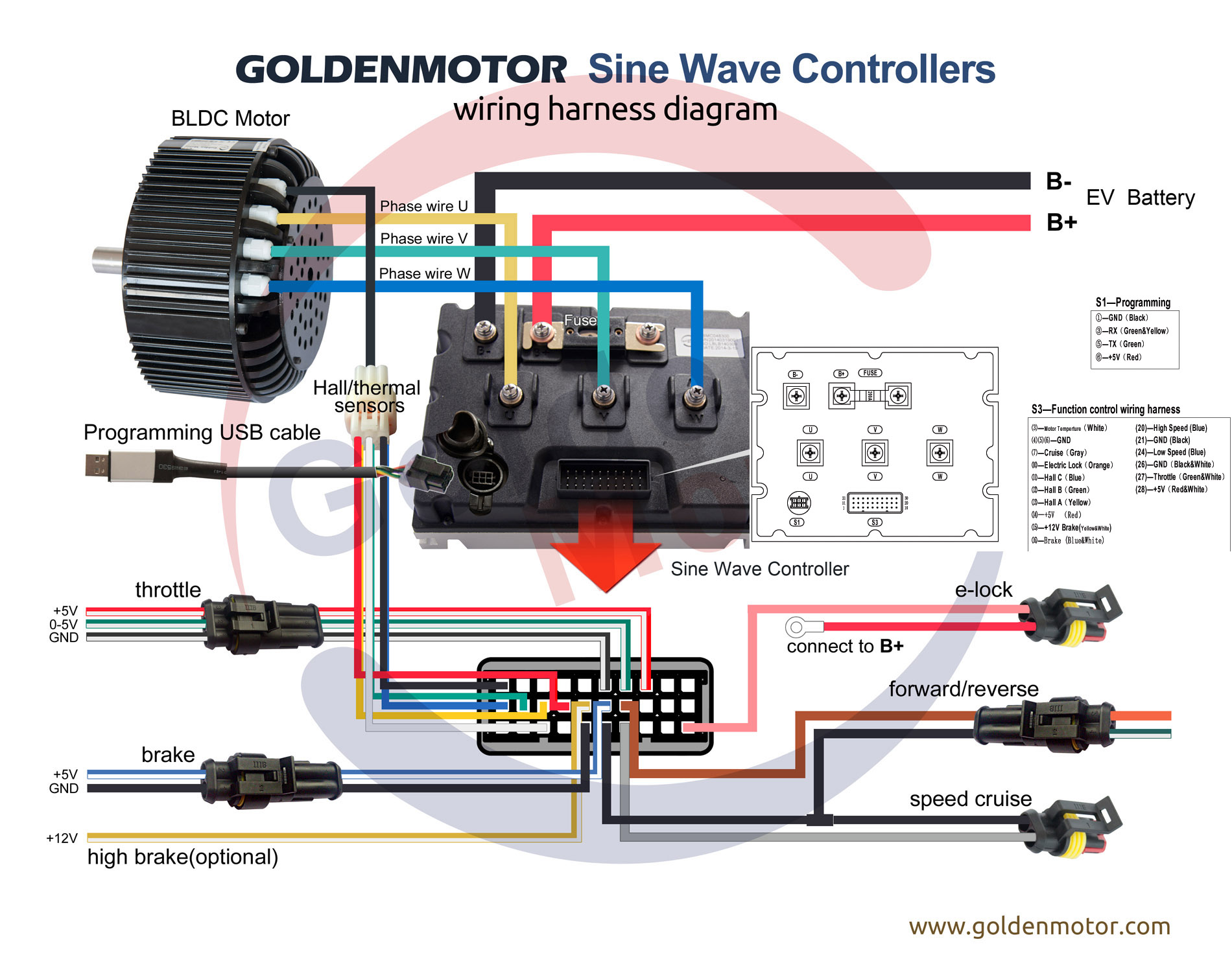
Brushless motors, BLDC Motor, Sensorless Motor, Motor … from www.goldenmotor.com
Hall sensor based motor commutation sequence timing diagram the underlying figure 4: The experimental work also shows that the speed control using field oriented control controls all the motor characteristics and makes the motor control easy. Soft starter circuit using microcontroller, soft starter for 3 phase induction motor using pic microcontroller 3 phase induction motor also reaches it full speed in minimum time or instantly.
Speed control — the synchronous motor frequency can be specified in real time to be any value from 1 hz to 128 hz by adjusting the pr2 potentiometer.
10+ 3 Phase Motor Speed Control Circuit Diagram. Speed control — the synchronous motor frequency can be specified in real time to be any value from 1 hz to 128 hz by adjusting the pr2 potentiometer. Speed control — the synchronous motor frequency can be specified in real time to be any value from 1 hz to 128 hz by adjusting the pr2 potentiometer. Often in the industry, need arises for controlling the speed of a 3 phase. The bars forming the conductors along the rotor axis are connected by a thick • favors system cost reduction by an efficient control in all speed ranges implying right dimensioning of power device circuits.