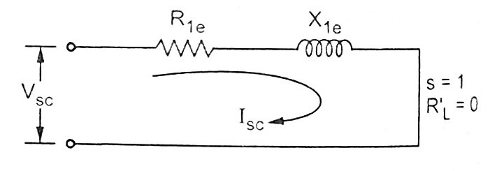
10+ Blocked Rotor Test Circuit Diagram. Connect the circuit as per diagram shown on attached sheet. Blocked rotor test this is similar to short circuit test in case of transformer.this test these 2 test are the best way by which you can obtain almost all the performance parameters.
Conduct no load test and blocked rotor test on the induction motor and find out the per phase. • the induced voltage is proportional with the difference of motor and synchronous speed. Equivalent circuit with phasor diagram.
I did some calculations, however i am not sure if what i am doing is correct.
10+ Blocked Rotor Test Circuit Diagram. Only the circuit's creator can access stored revision history. 4 circuit diagram circuit shown as per attached sheet for no load & blocked rotor test. I did some calculations, however i am not sure if what i am doing is correct. Blocked rotor test determines the leakage impedance and so the core losses.