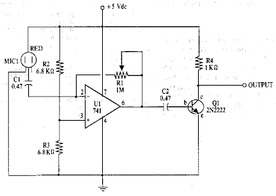
10+ Condenser Mic Circuit Diagram. In this circuit, the condenser mic becomes more sensitive that is used to catch the voice signals which i speak. Condenser mic is a type of capacitive audio sensor (audio transducer) that converts the sound (audio) signal into electrical signals.

Anything audio is something i'm very interested in i checked the individual components (in circuit) and everything seems to be in order, obviously i didn't remove any components wanted to make sure. It is known as clap switch because the condenser mic which will be used in this project will have an ability to take the sound having the same pitch as the clap sound as the input. There are a number of different models and finding an affordable one shouldn't be a problem.
The circuit is alienated into three divisions:
10+ Condenser Mic Circuit Diagram. The circuit is alienated into three divisions: Before we show the complete schematic diagram of the microphone amplifier circuit, we will first show the pinout of the lm386. It consists of a parallel plate capacitor formed by black plate and front plate. Anything audio is something i'm very interested in i checked the individual components (in circuit) and everything seems to be in order, obviously i didn't remove any components wanted to make sure.