10+ Flip Flop Schematic. As i said they pretty much look same to me,what cause them to work different, where is the difference in schematic? The q and qn outputs can change state only on.
Circuit Design (GPS) Part 6 from what-when-how.com
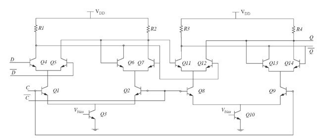
The rs latch flip flop required the direct input but no clock. The basic d flip flop has a d (data) input and a clock input and outputs q and q (the inverse of q). But what is a digital ?
With the help of boolean logic you can create.
10+ Flip Flop Schematic. When clk = 1 the master latch will be enabled and slave. Notice that when the clock signal is hi, the data on the d input is transparent to. A flip flop is a sequential circuit which consists of a single binary state of information or data. In first method, cascade two latches in such a way that the first latch is.