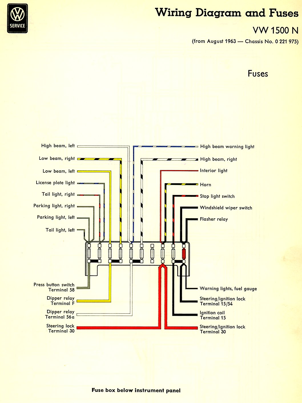
10+ Fuse Circuit Diagram. Home › electronic circuits › led blown ac fuse indicator circuit diagram. As shown in the circuit, it involves only few circuits and hence it is easy to construct.

Home › electronic circuits › led blown ac fuse indicator circuit diagram. 4.2 l v6, 4.6 l v8 or 5.4 l v8 30. This fuse indicator circuit makes an led light up if a fuse blows, this gives a quick indication if the fuse has blown and.
Fuso battery & sensors schematics.
10+ Fuse Circuit Diagram. As shown in the circuit, it involves only few circuits and hence it is easy to construct. It is typically an inline device that allows a certain amount of current to flow through it. Transistor t1 and resistor r1 form a 6 ma current source that, together with zener diode d1, provides a constant voltage of 5.6 v with respect to the +ve supply line. This fuse indicator circuit makes an led light up if a fuse blows, this gives a quick indication if the fuse has blown and.