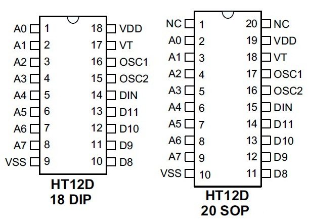
10+ Ht12D Pin Diagram. Vdd and vss are used to provide power to the ic, positive and negative of the power supply respectively. Holtek, alldatasheet, datasheet, datasheet search site for electronic components and semiconductors, integrated circuits, diodes, triacs, and other semiconductors.
It gets to interface with the third device this is a pinout diagram of a 12 bit rf decoder. Ht12e is a 212 series encoder ic (integrated circuit) for remote control applications. The serial data is fed to the rf transmitter through pin17 of ht12e.
A basic connection diagram for the ht12e ic is shown below.
10+ Ht12D Pin Diagram. Asignement of receiver direction, it mean it can changing of adresses for comunication individualy if is needed. Transmission is enabled by providing ground to pin14 which is active low. For the ht12a encoders, transmission is enabled by applying a low signal to one of the data pins d8~d11. Ht12e is a 212 series encoder ic (integrated circuit) for remote control applications.