10+ Lm324 Bass Treble Circuit Diagram. Pin diagram of lm324 comparator. The operating temperature ranges from 0˚c to 70˚c at.
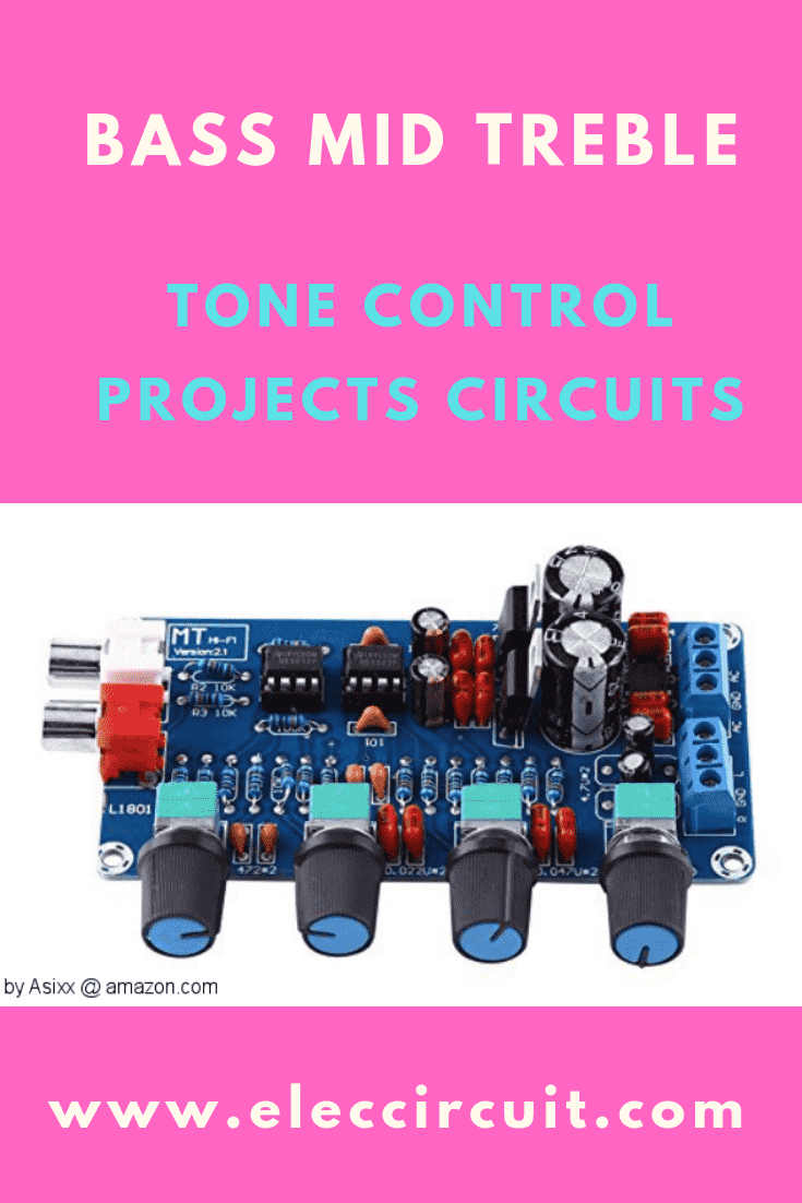
3 (bass mid treble) Tone control circuits projects using … from www.eleccircuit.com
The operating temperature ranges from 0˚c to 70˚c at. How to make bass circuit diagram? This input current only exists when the voltage at any of the input leads is driven negative.
In this post we are going to take a look at the popular lm 324 ic.
10+ Lm324 Bass Treble Circuit Diagram. If military/aerospace specified devices are required note 4: I used three lm 324 ic and two 4.7 k ohms resistors for voltage divider biasinig for all ic s 15k ohms n 10 k ohms and polyster capacitors for selecting frequency band to amplify or attenute u can mail me for circuit diagram. • low input noise voltage: For operating at high temperatures, the lm324/lm324a/lm2902 must be derated based on a +125˚c maximum junction temperature and a thermal resistance of 88˚c/w.