10+ Rlc Phasor Diagram. The rlc series circuit is a very important example of a resonant circuit. Phasor diagram of series rlc circuit.
Solved: 1) A Driven RLC Circuit Is Represented By The Phas … from d2vlcm61l7u1fs.cloudfront.net
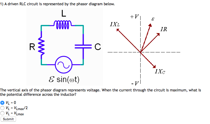
Figure 15.12 the phasor diagram for the rlc series circuit of figure 15.11. Its magnitude reflects the amplitude of the voltage or current, and. How can i make phasor diagrams for the circuit in case when $$i_c<i_l$$ and $$i_c>i_l$$.
Homework equations vc = 1/j\omegac.
10+ Rlc Phasor Diagram. Phasor diagrams are a representation of an oscillating quantity as a vector rotating in phase space with an angular velocity equal to the angular frequency of the original trigonometric function. The phase is the angular shift of the sinusoid, which corresponds to a time shift t0. Then to summarise this tutorial about phasor diagrams a little. Phasor diagrams are a way of representing sinusoidal waveforms such that you can add and phasor diagram is nothing but a graphical representation of sine wave with frequency and amplitude.