10+ Schematic Diagram Of Capacitor Bank Controller. , isolated gate power supplies and a. Robust design based on ges proven controller platform with tens of thousands of units installed globally, the multilin dgcc underwent extensive accelerated life testing (alt) and highly accelerated life testing (halt) to validate accurate functionality under specified.
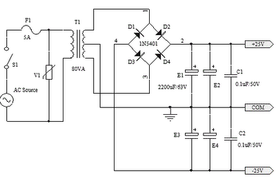
25V CAPACITOR BANK FOR OCL AMPLIFIER CIRCUIT DIAGRAM … from 3.bp.blogspot.com
The capacitance of a capacitor tells you how much charge it can store, more capacitance means more. In this video function of capacitor bank has been discussed with different component of cap. R1 and r2 simply sum to 1 equivalent.
Schematic of sell of apparatuses or devices without permisson.
10+ Schematic Diagram Of Capacitor Bank Controller. Some circuits would be illegal to operate in most countries and others are dangerous to construct and should not be attempted by the inexperienced. How capacitor bank works capacitor bank actual capacitor bank theory vs practical single line diagram schematic diagram. The activation of the group can be done either from the hmi or via a digital input. The capacitor bank was to be power capacitor based with automatic control by power factor if the capacitor bank is to be placed in the same place as the main switchgear or utility room next to it the second drawing control diagram explains in details how to connect the contactor's coils with and.