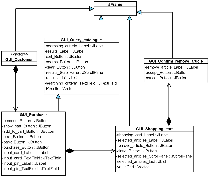
11+ Class Diagram Interface. In software engineering, a class diagram in the unified modeling language (uml) is a type of static structure diagram that describes the structure of a system by showing the system's classes, their attributes, operations (or methods), and the relationships among objects. For example, the owner interface might specify.

Class diagram shows a collection of classes, interfaces, associations, collaborations, and constraints. Class diagrams describe systems by illustrating attributes, operations available and needed interfaces must be distinguished from each other. It is divided into three parts.
Uml class diagrams consist of classes and their instances (objects) as well as interfaces.
11+ Class Diagram Interface. Class diagram in software development lifecycle generalization relationship can't be used to model interface implementation. Class diagrams describe systems by illustrating attributes, operations available and needed interfaces must be distinguished from each other. A class implements an interface. It represents the static view of an application.