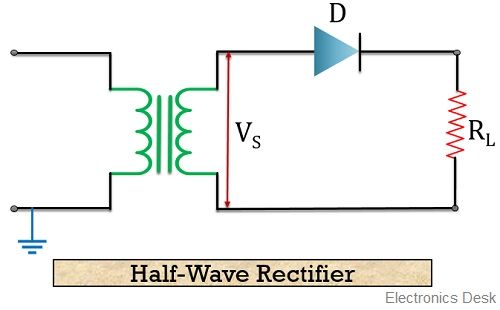
11+ Half Wave Bridge Rectifier Circuit Diagram. Like the half wave circuit, a full wave rectifier circuit produces an output voltage or current which is purely dc or has some specified dc component. In hwr, we use only one diode which is more than sufficient to the below diagram shows how the capacitor filter smoothens the waveform.

Bridge rectifier overall these three bridge rectifier gives better efficiency and ripple free dc. The circuit form a bridge connecting the four operation of full wave bridge rectifier. Unlike half wave rectifiers which uses only half wave of the input ac cycle, full wave rectifiers utilize full wave.
Many electronic circuits require a rectified dc power supply to power various electronic basic components among the rectifiers, the bridge rectifier is the most efficient rectifier circuit.
11+ Half Wave Bridge Rectifier Circuit Diagram. Diode rectifier circuits half wave rectifier full wave rectifier two diode full wave rectifier full wave bridge rectifier synchronous rectifier. The next kind of full wave rectifier circuit is the bridge full wave rectifier circuit. When an ac supply is switched on, the alternating voltage vin appears across the terminals ab of the secondary. As shown in the figure above, the bridge rectifier.