11+ Power Factor Meter Circuit Diagram. This circuit shows an inductor being driven by an ac voltage. I need your help in this circuit.
For sinusoidal signals the power factor is defined by. This is the power factor circuit diagram with the detailed explanation of its working principles. Digital volt & amp meter circuit diagram.
Circuit diagram of pf relay.
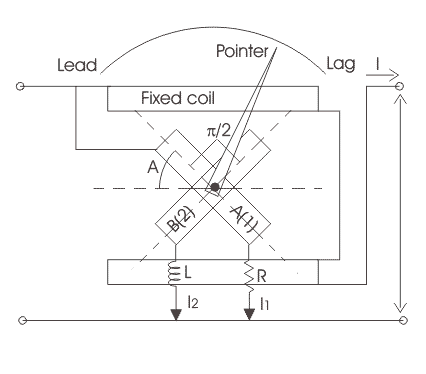
11+ Power Factor Meter Circuit Diagram. Note that the diagram is drawn for an inductive circuit. Energy meter block diagram 2000w power amplifier circuit diagram single phase class1 iec 61036 energy meter an2288 7818 ct digital energy meter. The power factor of an ac circuit is defined as the ratio of the real power (w) consumed by a circuit to the apparent power (va) consumed by the same in practical ac circuits, the power factor can be anywhere between 0 and 1.0 depending on the passive components within the connected load. Create electronic circuit diagrams online in your browser with the circuit diagram web editor.