11+ Voltmeter Selector Switch Connection Diagram. 2 analogue voltmeters & ammeters analogue s for commercial and industrial single phase : In this video we explain voltmeter connection with selector switch in general we can measure voltage by voltmeter switch in this video we explain single and three phase voltmeter connection for more information just watch and three phase dol starter control overload indicator power wiring diagram.
Rf selector switches would be found on short wave receivers and also check for voltage (12 volt) to the switch with the voltmeter. Tg 0258 three phase ammeter wiring diagram voltmeter selector switch avs diagrams tm 55 how to connect voltage and electrical smithy automate cnc. In this video we explain 3 phase digital voltmeter connection with selector switch, we know we can measure voltage with voltmeter.
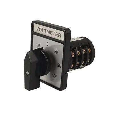
Be cool i also share the connection diagram for voltmeter selector switch wiring for 3 phase 4 wire system.
11+ Voltmeter Selector Switch Connection Diagram. The reading on the multimeter is simply negative. A complete guide of ammeter selector switch wiring diagram or rotary switch wiring diagram for 3 phase system load testing. Wiring accessories and building automation. If all is well to this point move to the roof motor and repeat tests.