12+ And Gate Ladder Diagram. Nor logical gate in ladder logic for plc. In the above circuit when a or b or both a and b are grounded or at 0v potential transistor in this ic there are also 4 gates together.
Basic NAND gate operation explanation using the electrical … from 1.bp.blogspot.com
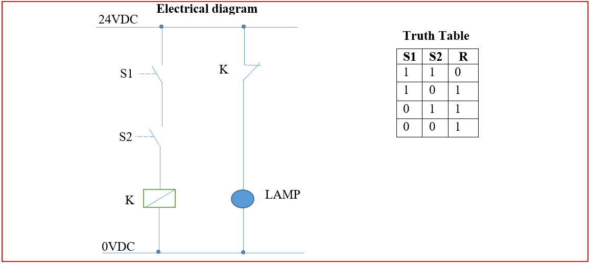
The transistor circuit diagram for an and gate is shown below: §§ if x1 or x2 remain open then c coil is unexcited and c contact remains closed plc programming. When both the inputs are high the output y0 is high.
Explain the basic digital logic gates circuit and boolean logic with plc programming.
12+ And Gate Ladder Diagram. Ladder diagrams (sometimes called ladder logic) are a type of electrical notation and symbology frequently used to illustrate how electromechanical ladder diagrams are specialized schematics commonly used to document industrial control logic systems. Simplify this logic gate circuit, which uses nothing but nand gates to accomplish a certain logic function In a special branch of mathematics known as boolean algebra, this effect of gate function identity changing with the inversion of input signals is described by demorgan's theorem. Back in sequence diagram 1, add another gate.