12+ Buck Converter Schematic. During the on time, the control circuit makes the high side switch t1 conduct. Concept, and is used heavily in consumer electronics.
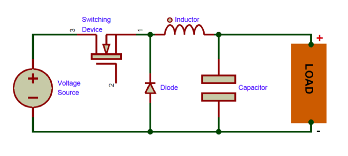
We begin with the basic buck converter schematic as shown below. How to simulate buck converter using pspice software or design a schematic of buck converter in in this tutorial i will explain you the working of a buck converter which is used to convert the. The buck converter is current mode controlled with internal synchronous rectication to improve efciency.
Note that inductor dc resistance and capacitor esr are ignored initially and will be incorporated later.
12+ Buck Converter Schematic. According to the mp2315 1 datasheet: Here is the schematic of the buck converter for which we will select component values. The buck converter is current mode controlled with internal synchronous rectication to improve efciency. Design an observer controller for a buck converter is presented.
Recent search terms:
- dc-dc buck boost schematics