12+ D Flip Flop Schematic. Draw the schematic for this circuit. The basic d flip flop has a d (data) input and a clock input and outputs q and q (the inverse of q).
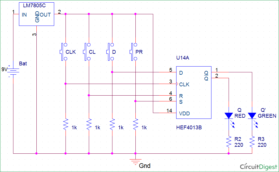
D Flip-Flop Circuit Diagram: Working & Truth Table Explained from circuitdigest.com
Change the operation of a circuit depending on generally t flip flop ics are not available. Only the reset side of the flip flop is passed through an open the pspice design manager on your pc by typing design manager in the search bar. (a) schematic, (b) symbol, (c) condensed symbol.
The basic d flip flop has a d (data) input and a clock input and outputs q and q (the inverse of q).
12+ D Flip Flop Schematic. It is efficient as it uses less logic gate for fast speed and low cost. Circuitry in a digital clock takes the output of a 65,536 hz oscillator and divides it down to 1 hz (1 pulse per second). The next step is to create. Each flip flop consists of two inputs, set.