12+ Full Wave Rectifier Circuit Diagram. Hence, this is a full wave rectifier. Circuit diagram of full wave rectifier.
Full Wave Bridge Rectifier operation with Capacitor Filter from electric-shocks.com
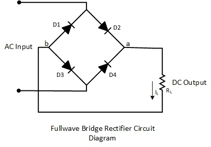
From the above diagram, we can see. A bridge rectifier is an arrangement of four diodes in a bridge circuit configuration which provides the same output polarity for either input polarity. Full wave rectifier is a circuit arrangement which makes use of both half cycles of input alternating current (ac) and convert them to direct current (dc).
We know that a diode allows electric current in only one direction.
12+ Full Wave Rectifier Circuit Diagram. Power supply design in the undergraduate curriculum. From the above diagram, we can see. The corresponding voltage across load is 12.43v because the average output voltage of the discontinuous waveform can be. Full wave rectifier is a circuit arrangement which makes use of both half cycles of input alternating current (ac) and convert them to direct current (dc).