12+ Solar Mobile Charger Circuit Diagram. This is the schematic diagram of solar powered mobile phone battery charger. The suggested flyback solar charger circuit with i/v checking was created by me bearing in mind the above criticality of a solar panel.
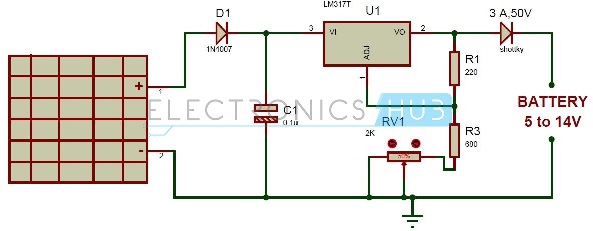
Solar Battery Charger Circuit using LM317 Voltage Regulator from www.electronicshub.org
The design has an operating efficiency of above 97% at full load in a 24v system. (or example, because a solar cell produces dc, which is what mobile phones generally require, if the solar cell ratings, as much as possible, closely matches the power requirements of the mobile phone, a transformer is not required The circuit diagram is divided into two major parts.
At the output of the charger, the.
12+ Solar Mobile Charger Circuit Diagram. I thanks to all of them for sharing their knowledge. Right here the ic 741 section is the current administering phase, the ic555. Now simply use any power cable and connect it to the usb pin of the module and the other. For example, because a solar cell produces dc, which is what mobile phones generally require, if the the design and construction requirements for this solar mobile phone charger are given below.