12+ Voltage Monitoring Relay Circuit Diagram. However, in practice this circuit has some shortcomings because the change in the indicated. Electronics tutorial about the relay switch circuit and relay switching circuits used to control a variety of loads in circuit switching applications.
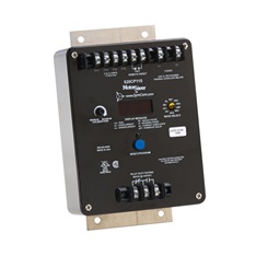
520CP115 – 520CS / 520CP Series – Current Monitoring … from www.littelfuse.com
We are really thankful for his contribution. 5 undervoltage monitoring relays usr. Circuit diagram of an electromechanical relay with components are given below relays are used to provide isolation between microcontroller's circuits and high voltage operating loads.
They together represent binary number.
12+ Voltage Monitoring Relay Circuit Diagram. A voltage sensor is a sensor is used to calculate and monitor the amount of voltage in an object. They together represent binary number. This diagram represents the basic circuit of solid state relays. In this video shows how to connection it'.