13+ 4017 Ic Diagram. The name suggest two things, it's something to do with number 10 and counting/dividing. The ne555 use as an oscillator.
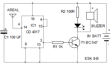
This is pin diagram of cd4017 counter.this 4017 counter ic is known as johnson counter ic. The ic 4017 is a versatile ic of the cmos family which has got wide range of applications. Pin assignments for dip, soic and sop.
When reset signal is applied the ic will reset and the output q0 will become high.
13+ 4017 Ic Diagram. It has two cd4017 decade counters (ic3 and ic4) and an ne555 timer (ic2). The cd4017 is a cmos decade counter ic. This is pin diagram of cd4017 counter.this 4017 counter ic is known as johnson counter ic. One place it can be obtained from for very cheap is tayda electronics at the following link: