13+ 8 Channel Relay Board Circuit Diagram. 8 channel relay board is a simple and convenient way to interface 8 relays for switching application in your project. Input supply 12 vdc @ 336 ma.
Internet of Things : Open Source Home Automation Project … from 2.bp.blogspot.com
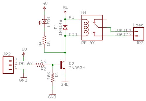
I was browsing on this website ,amongst others , to see if i could find a code for the project i need. Remotecontrolcircuit #remoteic #remotecontrolrelay remote control relay circuit friends, today in this video i am going to show. This video is the clip of 8 channel relay circuit using transistor.
Numato lab's 8 channel ethernet relay module is a versatile product for controlling electrical and the above image shows the basic connection diagram that can be used in most of the situations.
13+ 8 Channel Relay Board Circuit Diagram. A relay can be used to control high voltages with a low voltage by connecting it to an mcu. This video is the clip of 8 channel relay circuit using transistor. Remotecontrolcircuit #remoteic #remotecontrolrelay remote control relay circuit friends, today in this video i am going to show. The usb relay board is with 8 spdt relays rated up to 7a each.