13+ Hall Effect Circuit Diagram. If an electric current flows through a conductor in a magnetic field, the magnetic note that the direction of the current i in the diagram is that of conventional current, so that the motion of the hall effect can be used to measure the average drift velocity of the charge carriers by mechanically. This is known as hall effect.
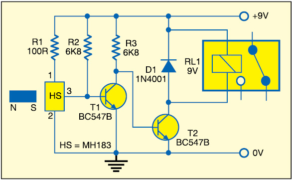
The hall effect was discovered by edwin hall in 1879 and has since been extensively applied in measurements, especially in figure 1. The circuit diagram shown here is of a hall effect switch. The device consists of a linear hall sensor circuit with a copper conduction path located near the the product of the linear ic amplifier gain (mv) and the noise floor for the allegro hall effect linear ic.
A hall effect switch will turn on in the presence of south magnetic field on its face or north magnetic field on the opposite side.
13+ Hall Effect Circuit Diagram. The hall effect sensor we will use in this circuit is an a1302 hall effect sensor manufactured by allegro. This ic can detect magnetic fields. It's output connected to the base of the transistor bc547. Permanent magnet temperature estimation in pm synchronous motors using.
Recent search terms:
- схемы на основе датчика холла A3144