13+ Hall Effect Sensor Circuit Diagram. As you can see, the hall effect sensor arduino circuit diagram is pretty simple. A hall effect sensor works on the principle of, well, hall effect.
Non-Contact Current Sensor Circuit Using Hall-Effect IC … from 2.bp.blogspot.com
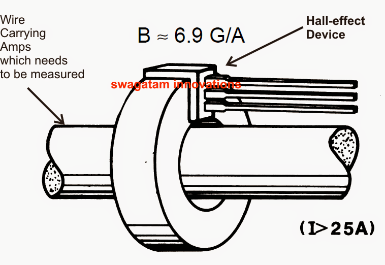
The pin out of hall effect current sensor is given below. Although the hall effect sensor acts like a relay, it has two specific advantages. A hall effect sensor is a sensor which detects magnetic fields.
Hall effect sensors uses this phenomenon of hall effect for sensing fundamental quantities such as position, velocity, polarity etc.
13+ Hall Effect Sensor Circuit Diagram. A hall effect switch will turn on in the presence of south magnetic field on its face or north magnetic field on the opposite side. Its output voltage is directly proportional to the magnetic field strength through it. This circuit diagram constructed by using simple and easily available components. When a magnet is placed in the vicinity of the a1302 hall effect sensor, we will see a reading change in the output, signaling that it knows a.