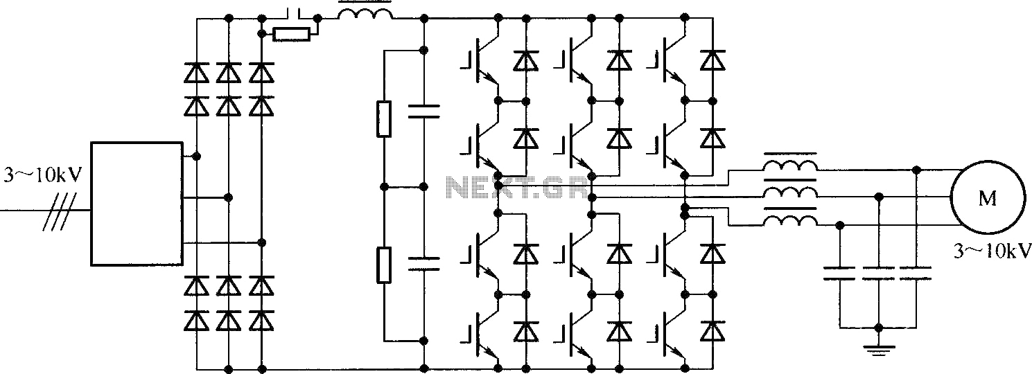
14+ Igbt Inverter Circuit Diagram. The inverter draws current from the driver during the on time of the mosfet, lowering the efficiency of the circuit. Igbt power losses ininduction heatingapplications.

Mig/mma dual function igbt inverter technology compact welding power source. Three phase waveform generated by arduino. In this video we take a look at variable frequency drives to understand how they work in electrical.
Igbt inverter welding, how to repair circuit , paano ayusin ang inverter welding machine.
14+ Igbt Inverter Circuit Diagram. Inverter circuits are electrically connected to the mains. Iweld mig 200 igbt manual online: The insulated gate bipolar transistor also called an igbt for short, is something of a cross between a conventional bipolar junction transistor, (bjt) and a field effect transistor, (mosfet) making it ideal as a semiconductor switching device. The igbt transistor takes the best parts of these two.