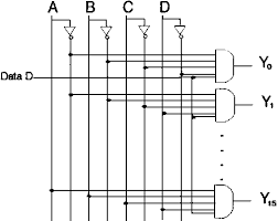
15 Demultiplexer Circuit Diagram. The idea is that you select one of the outputs and route an input signal to it. It receives one input and distributes it over several outputs.
Boolean expression of 1 to 8 demultiplexer 5. You will understand more clearly with the help of it connection diagram. Conversely, a demultiplexer (or demux) is a device taking a single input and selecting signals of the output of the compatible mux, which is connected to the single input, and a shared selection line.
A demultiplexer does the reverse operation of multiplexing.
15 Demultiplexer Circuit Diagram. 1 into 12 demultiplexer circuit diagram nortel demux 1 into 4 demultiplexer circuit diagram ya20 ya19 ya18 ya08 ac10 ab89 text: A demultiplexer performs the reverse operation of a multiplexer i.e. Here d0, d1, d2, and d3 are data input lines. Tpd = 16ns (typ.) at the m74hc154 is an high speed cmos 4 to 16 line decoder/demultiplexer fabricated with.