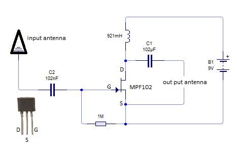
15 Fm Antenna Booster Circuit Diagram. This is the active fm receiver antenna amplifier, used to boost the fm signal catch by the antenna, you may call circuit fm antenna booster. Schematic diagrams are usually utilized for the maintenance and repair of electronic and electromechanical devices / units.
How to make 1000MHz signal booster device from 1.bp.blogspot.com
It must have the ability to transfer energy from electrostatic to electromagnetic, if the impedance match is correct, the energy will here we are designing the 2.4 ghz antenna for esp8255 mini board, so below is the circuit diagram for the same. Schematic diagrams are usually utilized for the maintenance and repair of electronic and electromechanical devices / units. This active fm amplifier circuit is reliable, and it only requires a few components.
Schematic diagrams are usually utilized for the maintenance and repair of electronic and electromechanical devices / units.
15 Fm Antenna Booster Circuit Diagram. The circuit shown here is of a tv antenna booster based on the transistor bf180. All inductors are air cored. An antenna amplifier boosts a radio signal considerably for devices that receive radio waves. This low cost antenna booster is simple and easy to build.it use single transistor.