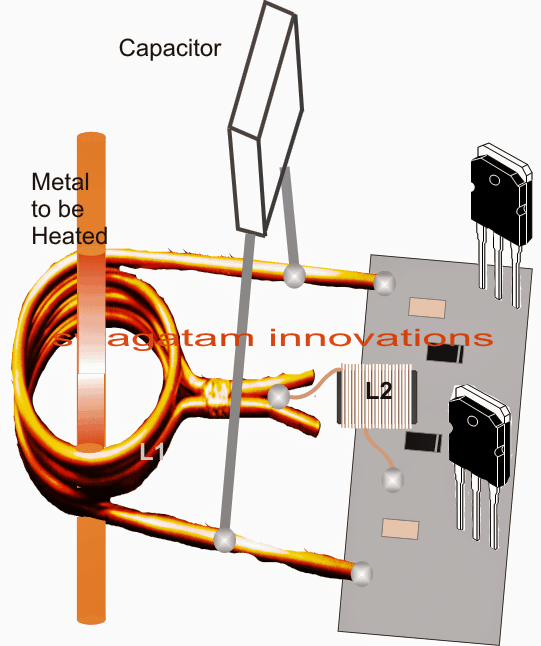
15 Induction Heating Circuit Diagram. The setup used for the induction heating process consists of an rf power supply to provide the alternating current to the circuit. Induction heating is the process of heating an electrically conducting object (usually a metal) by electromagnetic the two basic circuit configurations are as under:
2 Simple Induction Heater Circuits – Hot Plate Cookers … from homemade-circuits.com
➡ about eew electrical engineering world is the worldwide community with members engaged in the. Don't have much time to chose another project. Use a potentiometer with plastic shaft.
The setup used for the induction heating process consists of an rf power supply to provide the alternating current to the circuit.
15 Induction Heating Circuit Diagram. A typical induction heater system includes a power supply, impedance matching circuit, tank circuit, and lead design: Induction heating system image hd image of induction heating fig. As shown in the diagram, these eddy currents flow against the. Induction heating circuit datasheet, cross reference, circuit and application notes in pdf format.