15 Ne555 Timer Circuit Diagram. Right to make changes — philips semiconductors reserves the right to make changes in the products—including circuits, standard cells, and/or software—described or contained herein in order to improve design and/or performance. The output circuit is capable of sinking or sourcing current up to 200ma.
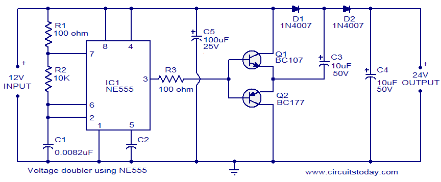
Electronic Communication Projects: Voltage Doubler Using 555 from www.circuitstoday.com
In this circuit, we have four basic blocks, these are 1. A popular version is the ne555 and this is suitable in most cases where a '555 timer' is specified. Motion detector using ne555 timer.
The below list from circuit digest consists of a huge collection of 555 timer circuits with neat circuit diagram and practical diy hardware explanation enabling you build.
15 Ne555 Timer Circuit Diagram. The 555 timer is an integrated circuit, it is extremely versatile and can be used to build lots of different circuits. But initially it is connected to ground. Applications of 555 timer circuits. Mpide debouncing uno32 uc32 max32.