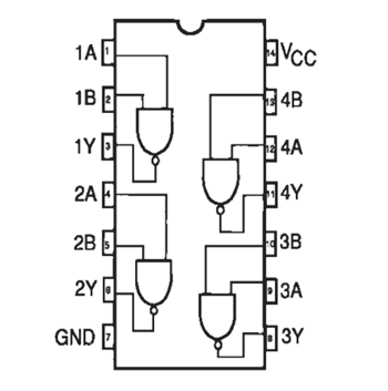
15 Not Gate Ic Pin Diagram. 74ls ic series comes up with multiple gates. Typically, standard logic gates are available in 14 pin or 16 pin dil (dual in line) chips.

Logic flow schematic diagram of not gate: This gate can have minimum 2 inputs but output is always one. They are complex circuits which have been etched onto tiny chips of semiconductor (silicon).
Logic nor gates are accessible victimization digital circuits to supply the specified logical operate and is given a logo whose form is that of a customary gate with a circle, generally referred to as associate in nursing inversion bubble at its ttl logic nor gate.
15 Not Gate Ic Pin Diagram. The ic 7404 consists of fourteen pins each pin are shown here. In this ic there are fourteen pins. And gate produces an output as 1, when all its inputs are 1; The silicon chip is usually packaged in a plastic holder with pins spaced on a 0.1 (2.54mm) grid which will fit the holes on stripboard and breadboards.