15 Temperature Measurement Using Thermistor Circuit Diagram. Temperature measurement in today's industrial environment encompasses a wide variety of needs and applications. The thermistor is mounted near the circuit component like copper meter coil which experiences the same temperature changes of the circuit.
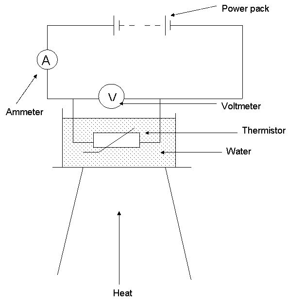
To use a temperature sensor in a control or compensation circuit, the detection circuit must provide an output this is commonly achieved by reading the measurement as a voltage using an analog to digital both thermistors and rtds have the flexibility to easily provide either a resistance or voltage. The circuit uses a bridge circuit, and the thermistor shown in the above figure is more sensitive and gives the accurate measurement. Thermistor is a very cheap, inexpensive and accurate sensor.
When a potentiometer is used instead of a thermistor, the application can also be used to measure other.
15 Temperature Measurement Using Thermistor Circuit Diagram. The resistance r of a thermistor at temperature t can be modeled by. Definitions the following terms are used in this application note: • enable thermistor circuit • read the adc channel connected to the temperature sensor and convert this to. Thermistors are constructed from a ceramic type semiconductor material using metal oxide temperature sensors example no1.