15 Transistor Equalizer Circuit Diagram. It is designed around the lm833 opamp from national semiconductors. We use it for controlling the audio frequency in some kinds of audio the high quality circuit uses minimum components with a low cost and ideal for beginners.
Repository-circuits Page 227 :: Next.gr from www.next.gr
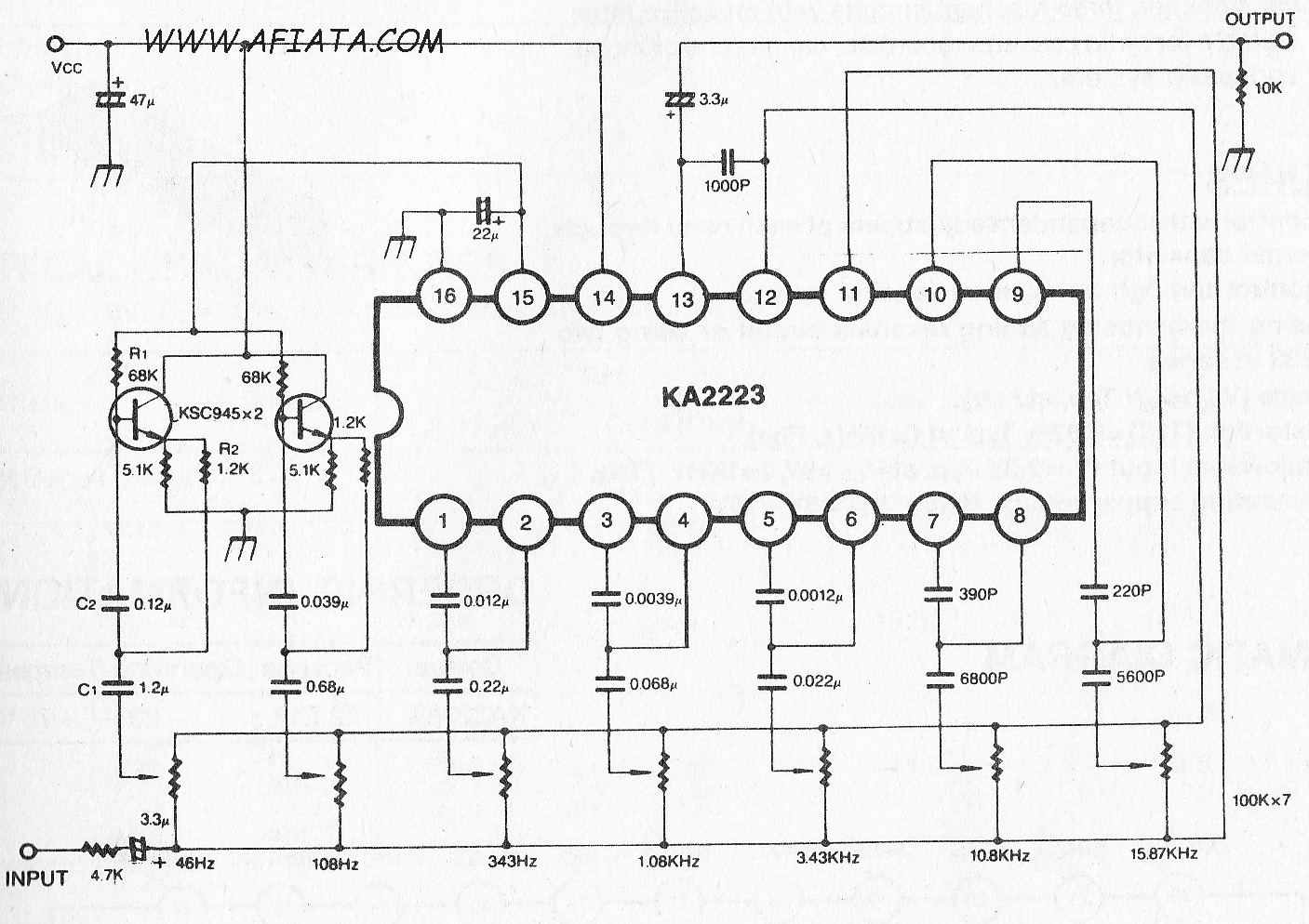
This equalizer circuit can be adjusted the frequency to 5 channel is 60 hz, 100 hz, 1 khz, 3 khz, and 12 khz. Transistor circuit design tutorial includes: It is composed of semiconductor material usually with at least three terminals for connection to an.
Transistor circuit design tutorial includes:
15 Transistor Equalizer Circuit Diagram. And, this project consists of stereos, right and left channel. This transistor ignition circuit give your car to have better starting and smoother running, particularly at very high and very low rpm. Amplifier is a circuit that is used for amplifying a signal. Booster amplifier circuit diagram :