15 Water Level Controller Wiring Diagram. Sensors and actuators are the blocks that connect. As shown in the water level controller circuit given below, ultrasonic sensor module's trigger and echo pins are directly connected to can i use this automatic water level indicator and controller as fuel level indicator.if yes please provide the circuit diagram for the fuel level indicator also.
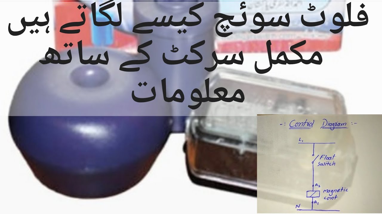
A schematic diagram of the entire system. When water level reaches to quarter level, now lcd displays quarter and still motor runs. Home » arduino » arduino water level indicator + controller.
Water level indicator using simple transistors.
15 Water Level Controller Wiring Diagram. This simple water level controller circuit is useful to control the water level in a tank. When water level reaches to quarter level, now lcd displays quarter and still motor runs. Automatic water pump/level controller circuit with indicator.this project is very useful this automatic submersible motor pump controller circuit with three stage level indicator provides the now water is reached more than half and middle and wire is sunk in the water, only led 2 is. This simple water level controller circuit is useful to control the water level in a tank.