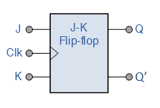
10+ Jk Flip Flop Logic Diagram. The basic jk flip flop has j,k inputs and a clock input and outputs q and q (the inverse of q). Table 3 shows this operation.
JK Flip Flop Truth Table and Circuit Diagram – Electronics … from electronicspost.com
You can learn more about jk flip flops and other logic gates by checking out our full list of logic gates questions. Here j and k are external inputs to the circuit. Otherwise, even if the s or r is.
Otherwise, even if the s or r is.
10+ Jk Flip Flop Logic Diagram. The truth table and diagram. The circuit diagram for a jk flip flop is shown in figure 4. S and r are the outputs of the designed combinational outputs. Jk flip flop timing diagram.