11+ Ups Inverter Circuit Diagram. Modern three phase ups designs often require: The power conversion from direct current to alternate current was accomplished in the middle of 19th to 20th century with the help of mg sets (motor generator sets) and rotary converters.
4 Simple Uninterruptible Power Supply (UPS) Circuits … from homemade-circuits.com
Its power is measured in watts or in inverter features & functionality description the project presented is really a 2kw or 2kva power inverter created for backup throughout utility and. Followings are the basics difference i want circuit diagram books of on line ups ranging from 1 kva to 30 kva single/ three phase of any your article is good and very helpful. When there is no ac supply outlet, we.
The following article about the inverter, to meet the demands of my previous colleagues, who wanted 12volt input voltage, output of 42 volts.the principle is the same with the inverter by using a transformer psu 12v to 220volt or 12volt to 110volt.
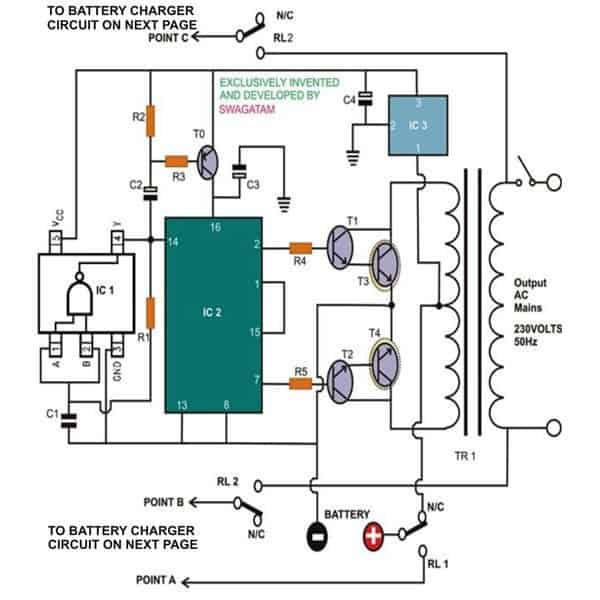
11+ Ups Inverter Circuit Diagram. Higher performance and reliable igbt and mosfet gate drivers. Above block diagrams are self explanatory. Ups is a system which converts dc to ac. Given ups schematic circuit diagram with its component list is a complete guide to build standard power backup.