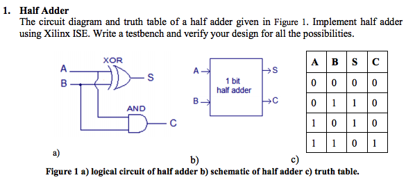
14+ Half Adder Circuit Diagram. Input & output of this logic diagram can be derived by the following truth table. The full adder circuit diagram is shown below

Half adder ad full adder. So what other ways are there of drawing a. After the discovery of digital electronics, similar operations are among those 1 and 0, 1 is treated as the largest digit and 0 as the smaller one.
Earlier there are various operations performed in analog circuits.
14+ Half Adder Circuit Diagram. Traffic light control electronic project using. This is the simplest of all the other possible designs of half adder. Traffic light control electronic project using. The total value of the sum of a half adder is equal to 2c+s.