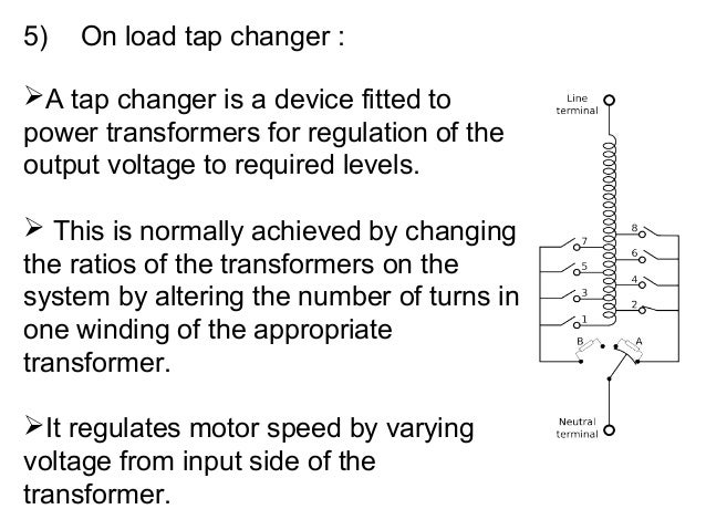
14+ On Load Tap Changing Transformer Circuit Diagram. N0 is the nominal number of turns. On load tap changer (oltc) is provided in the grid transformer to regulate the secondary voltage of the transformer where ;

Tap changing transformer causes changes in leakage reactance, core loss, i2r loss and perhaps some problems in parallel operation of dissimilar transformers. Reactors (inductors) are used in the circuit to increase the impedance of the selector circuit and limit the amount of current circulating due to this voltage difference. In the diagram, the on load tap changer is connected to tapping 4 while changing from tap position 4 to tap position 5, m1 is opened first and.
On load tap changers are used in liquid immersed electrical transformers in the power engineering industry.
14+ On Load Tap Changing Transformer Circuit Diagram. Dtr transformer tap changer controller. The function of the reactor is to prevent the short circuit of the tap winding. The purpose of the tap changer is to regulate the number of secondary windings within the circuit. On load tap changers are used to change the turns ratio without disconnecting the load from it.