15 Phasor Diagram Of Lcr Circuit. Suppose resistance r, inductance l and capacitance c are connected in series and an alternating. Know about series lcr circuit, its operation and phasor diagrams, inductors, and alternating current.
Driven RLC Circuit Using Phasors – GeoGebra from www.geogebra.org
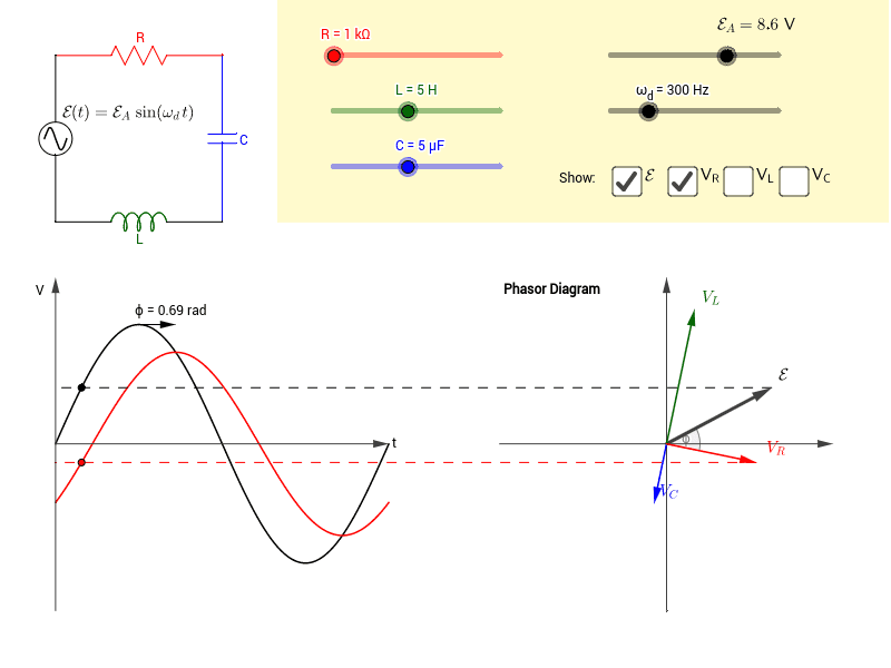
Suppose resistance r, inductance l and capacitance c are connected in series and an alternating. As shown in the phasor diagram, the voltage across the inductor l is leading the current with a phase 2π. To find the peak voltage of the circuit, we take the help of a phasor diagram where the phase relationship of the voltage with the current for all the three elements is clearly represented.
For a current, i = i cos ωt.
15 Phasor Diagram Of Lcr Circuit. An ac source of voltage v=vm sinωt is applied across a series lcr circuit. The lcr meter measures the impedance of the component or circuit at its terminals. I = i cos(ωt) and v = l di = −ilω sin(ωt). Move the sliders to change component values.