15 Pure Sine Wave Inverter Circuit Using Ic 4047. The square wave generated by this circuit can be easily converted into sine wave using few resistors sine wave generator circuit diagram using ic 4047_0. Here we use cd 4047 ic from texas instruments for generating the 100 hz pulses and four 2n3055 transistors for hi jeffreywong you can use sine wave oscillator circuit appeared in circuits today using icl3038 with or sir can send a pure sine wave inverter circuit to my mail box?
Scematic Diagram Panel: Pure Sine Wave Inverter Circuit … from 1.bp.blogspot.com
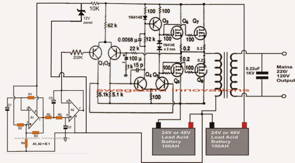
It has also an overload protection using a tlc272 operational amplifier. For this project i built a pure sine wave(psw) inverter using a high frequency(hf) design. The high power pure sine wave inverter/charger is a transformer based inverter and battery charger with an unprecedented conversion efficiency of 90%.
The following ideas may help you to achieve your.
15 Pure Sine Wave Inverter Circuit Using Ic 4047. I am just going to learn pcb circuit building from a 400l guy when i. Sine wave inverter circuit diagram using microcontroller, arduino and program code, spwm pure sine wave inverter circuit of spwm. The above 4047 sine wave inverter circuit was also tried successfully by mr. The hardware side of such an inverter is where you yes, but a pwm inverter is not necessarily a pure sine wave inverter.